The package contains a simple scene and demo assets. The following section describes the steps taken to produce the demo scene.
- Create a terrain or other object to place the boundary upon, and assign it a unique layer.
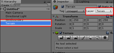
2. After importing the package, use the Tools > Boundary Builder menu to open the Boundary Builder Editor Window:
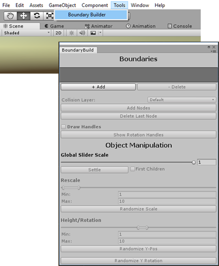
3. Click the [Add] button to create a new Boundary GameObject.

4. Provide a name for the boundary, and click [OK].

5. In the Editor window, select the Collision Layer you chose in the first step:
- This layer is used to detect which layer to place boundary nodes upon in the scene view.
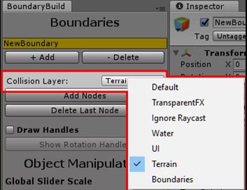
- Toggle the [Add Nodes] | [Delete Nodes] | [Insert Nodes] buttons in the scene view to activate a placement mode:

2. Left-click the collision object in the scene view to define boundary nodes:
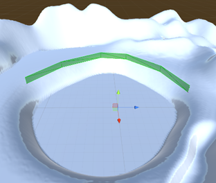
Notice each selected boundary has a unique inspector. Beneath the Boundary Control section, there are various values used to configure visibility, mesh generation, and behavior.
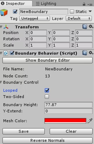
- [Show Boundary Editor]: Opens the Editor Window.
- File Name: Unique name of this boundary, used for loading and deleting data.
- Looped: Closes the boundary loop between the last node and the first.
- Two-Sided: Generates mesh faces on both sides of the boundary mesh.
- Boundary Height: How high above boundary nodes the mesh should extend.
- Y-Extend: How far below boundary nodes the mesh should extend.
- Mesh Color: Rendered mesh color in scene view.
- [Save]: Adds/Updates Mesh Renderer and Mesh Collider components.
- [Clear]: Clears boundary nodes and Mesh components.
- [Reverse Normals]: Reverse the mesh normals if single-sided.
3. The Editor Window has settings to move or rotate boundary nodes.
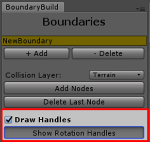
- Enable the “Draw Handles” checkbox to view handles.
- Toggle [Show Rotation Handles] to show rotation handles instead.
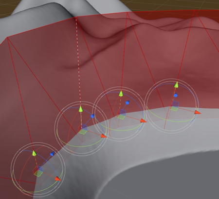
Note: A white dotted line shows the position of the last-created boundary node.
Boundary ScriptableObject data and mesh assets are saved at BoundaryBuilder/Resources, with a sub-folder for each boundary name.
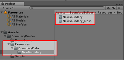
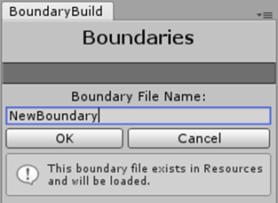
If you delete the boundary from your scene hierarchy, or wish to add the boundary to multiple scenes, simply create a new boundary with the same name as the boundary asset file. A notification will be shown when data will be loaded instead of created new.
Use the [- Delete] button in the Editor Window to entirely remove the scene object(s), boundary data, and mesh asset from project directory.
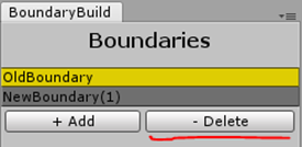
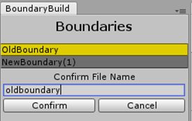
To confirm deleting of data, type the boundary’s filename and click [Confirm].
After a boundary is first saved, (using the [Save] button on the inspector), Mesh Renderer and Mesh Collider components are added to the scene GameObject.
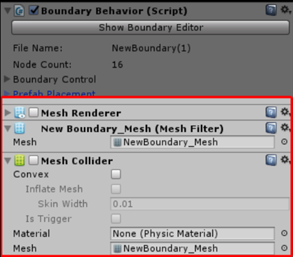
- Enable the Mesh Collider as needed for physics or trigger-based interaction.
- Enable the Mesh Renderer and Mesh Collider both before baking a NavMesh if the boundary is to affect navigational area(s).
- Click [Save] after the boundary is updated in the scene view using transform handles. This ensures the Mesh Collider has the most recent version of the mesh.
Establish a boundary within the scene using the Editor Window and Boundary Behavior Inspector as described previously.
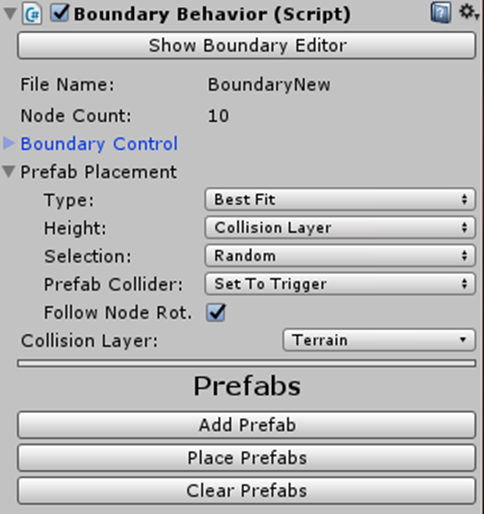
The “Prefab Placement” category has controls to add and configure prefabs. The following settings determine the methodology used to place objects:
- Type
- Best Fit: Places prefabs between nodes as best as they will fit – a basic, straightforward method.
- Post and Fill: Allows setting each prefab as either “Post” or “Fill.” A “Post” prefab is placed at each node position, and “Fill” prefabs are used between nodes
- Height
- Point To Point: Prefabs are placed directly along the line between two nodes.
- Collision Layer: Each prefab location is tested against the terrain surface, rotated and translated accordingly.
- Selection
- Random: Prefabs are selected randomly. If the Type is set to “Post and Fill,” objects will be randomly selected among those of the same type i.e. A random “Post” object will be placed at each node from among all objects marked as “Post.”
- Efficient: The prefab that takes the largest amount of remaining room is placed until reaching the next node.
- Prefab Collider
- Delete: Remove Box Collider component from prefab root transform after placement.
- Set to Trigger: Enable “Is Trigger” setting on prefab collider component after placement.
- Follow Node Rotation – When enabled, prefabs will tilt to the “left or right” to best follow the shape of the boundary mesh.
- Collision Layer – Similar to the layer selected in the Editor Window, this layer is used to position prefabs on a collision surface.
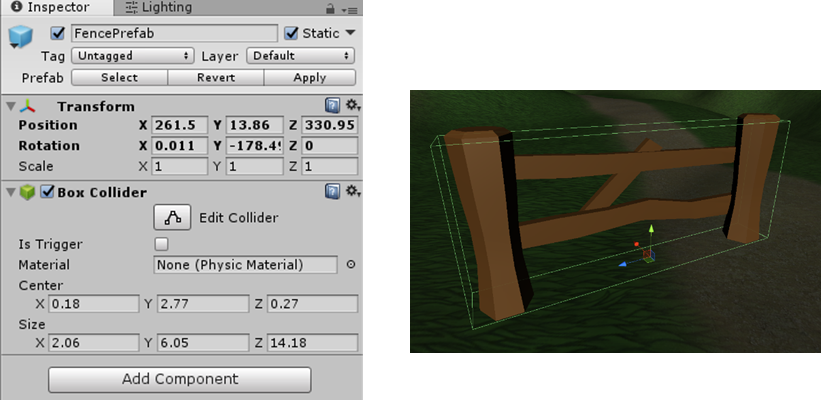
Each prefab should have a Box Collider component at its root transform that defines the prefab’s physical extents. Boundary Builder uses the size of this collider to place prefabs that do not overlap, so prefabs will not be placed without a Box Collider component.
- On the prefab object, use the [Add Component] menu to add a Box Collider component to it, size the collider appropriately, and save the prefab in your project hierarchy.
2. Select the boundary in the scene hierarchy or BoundaryBuild Editor Window, and click the [Add Prefab] button.
A new section will appear to configure the new. Drag & Drop the prefab from the project hierarchy to the GameObject reference slot, or use the target selector to do so using the asset list.
3. With the default settings (Best Fit, random selection, etc.), pressing [Place Prefabs] at this point should place the prefab wherever it will fit on the boundary. If the prefab is not placed, it is either missing a Box Collider, or the prefab will not fit between any nodes.
Each prefab has some controls beneath it that affect all spawned prefabs in the scene.
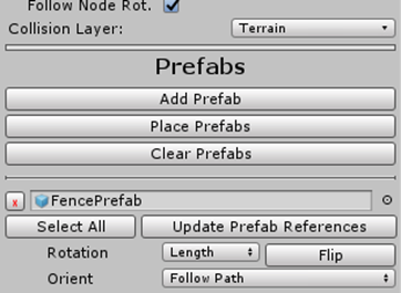
[Select All]: Selects all prefabs of that type.
[Update Prefab References]: After applying changes to a prefab, you may notice the boundary prefabs do not conform immediately. This is because they are clones, so clicking this button will sync the scene prefabs with their parent.
[Rotation] (Length, Width, Random): Controls the prefab’s Y-Rotation along the boundary.
[Flip]: Flips the prefab along its X-Axis.
[Orient] (Follow Path, Straight Up): Controls the prefab’s X-Rotation along the boundary path.
Once prefabs are placed, additional “Object Manipulation” can be done in the Boundary Editor Window. The following functions are applied to selected objects within the scene:
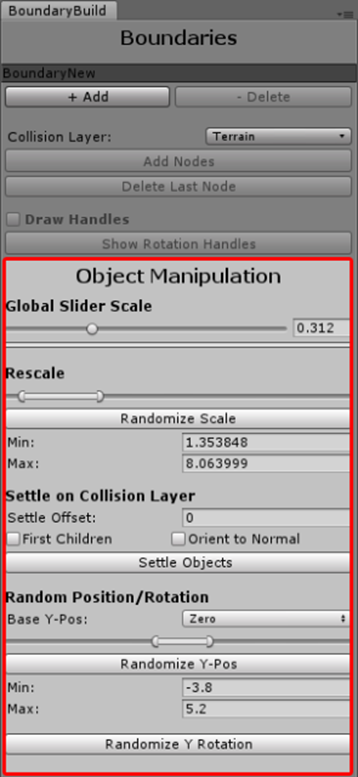
Note: The “Global Slider Scale” value controls the size of all sliders within this section.
[Rescale]: Randomly scales the selected objects between the designated minimum and maximum factors.
[Settle on Collision Layer]
- Settle Offset: Amount added to y-position after object is settled on collision layer.
- First Children: Enable this to settle the first-level child transforms of the selected object instead of the selected object itself.
- Orient to Normal: Enable this to rotate each object after being settled to have an upward direction matching the collision layer normal.
- [Settle Objects]: Casts a ray beneith each object (taking their rotation into account), and repositions the object onto the collision layer if hit.
[Random Position/Rotation]
- Base Y-Pos: Determines the point used to randomize around. If “Zero,” world-space zero is used. If “CollisionLayer,” the object’s Y-position on the collision layer will be used.
- [Randomize Y-Pos]: Randomizes the Y-position of all selected objects between the min/max, based on “Base Y-Pos” value.
- [Randomize Y Rotation]: Applies a random rotation about the Y-axis.
