This tutorial will detail the basic steps in setting up a generated modular object. Note that the DemoScene contains a very working example of using ProcMod to generate entire scenes, which can be saved and loaded in a way that they persist even after changing Unity scenes.
After importing the asset into your project, copy the “ProcMod/Gizmos” folder into your Assets folder (or copy all the items from that folder into an existing Assets/Gizmos folder).
Use the following steps to create a new procedural item:
- Create prefabs for each section of the item, with one or more box collider components at the root of the prefab. The colliders are used by the system to determine the extents of the item.
- All box colliders at the root of each prefab will by default be deleted by the ProcMod system when the item is “finalized.” (This can be controlled programmatically.)
- Note: Root prefab objects should be on a unique layer to properly check for collision with other modules.
- Right-click in the Project Navigator (or use the “Assets” menu item), then choose:
ProcMod > ProcMod System
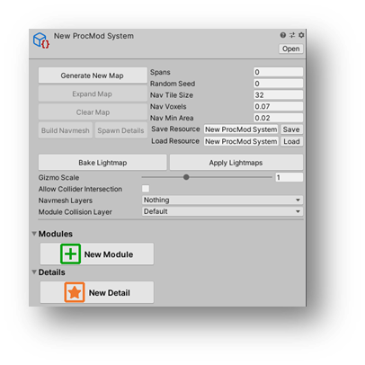
- This will create a new scriptable asset that shows a custom inspector when selected:
3. Configure system properties.
- Gizmo Scale: World scale of scene gizmos belonging to ProcMod.
- Allow Collider Intersection: If enabled, the system will check for module intersection before placement.
- Navmesh Layers: Layers navmesh should include when baking navigation.
- Module Collision Layer: Layer used to check for module intersection.
4. Click “New Module” in the ProcMod asset inspector to add a new module slot. Drag the prefab from the Project Hierarchy into the ‘Prefab Object’ reference - perform this action for each prefab section.
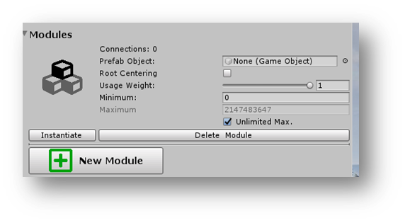
Note: Adding modules to a ProcMod system will modify the prefab to include a “ModuleTag” component.” This component is used to identify a prefab as belonging to the ProcMod system.
Properties:
Root Centering: After generation, the instantiated modules in the item are parsed and the entire item will be centered around the first “root centering” module’s world position.
Usage Weight: A value between zero and one used to determine the likelihood this module is used during generation relative to all other modules in the system.
Minimum: An integer value used to control the minimum number of this module type to instantiate during generation. Depending on the setup, this may be an impossible number to meet, but the system will basically choose this module whenever possible until the minimum is met.
Maximum: Similar to minimum, this value is used to control the maximum number of instantiated modules of this type to include during generation.
Functions:
[Instantiate]: Creates a new root system GameObject in the scene if not already present, and instantiates this module within it.
[Delete Module]: Removes this module from the system, and deletes all connections to it from other modules.
- Instantiate two modules into an empty scene to begin creating connections. Position the two modules in a way that they might connect.
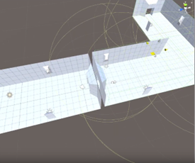
2. Select both instantiated modules in the scene, and the ModuleTag script will change to represent the selection:
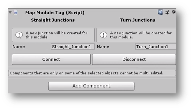
A gizmo in the scene view will be positioned at the nearest point between the two modules, with a teal-colored sphere. This shows where the module connection (junction) will be created, and can be moved within the scene view as necessary.
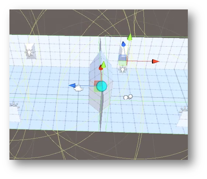
3. Click [Connect] to connect the two modules, and “Connected” will appear on the tag component.
Important Note! A “junction” has now been created for each of the two modules at the gizmo location. At first, this may be confusing, especially when connecting a module to itself.
Many other modules can be connected to a module from a single junction. During generation, each junction is checked, and one of the connected modules is chosen from among the connected modules. Using the colliders on the chosen module, the scene is checked for intersection with other modules before the new module is added to the scene. Generation then continues by checking each of the new module’s junctions and instantiating further connections.
If it is possible the same two modules can be connected in a different orientation, reposition the modules in the scene view.
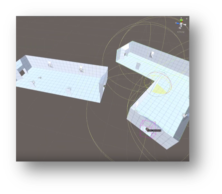
To create a new junction for the module you just repositioned, change that module’s junction dropdown to “(Create New),” and click [Connect] again to create a new connection.
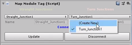
Once all modules are connected, remove from the scene any instantiated modules or objects to test. Then select the ProcMod asset in the Project Hierarchy to view its inspector.
The “Spans” value controls the maximum number of iterations performed during generation. Set it to something greater than zero, and click [GENERATE]. An object will be added to the scene with the same name as your ProcMod asset. This root object will then contain the modules generated for the item.
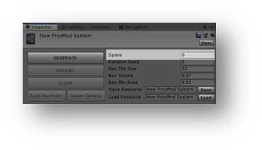
[EXPAND] can be used to continue adding single spans to the item if possible after initial generation.
After connections are made to a module, the inspector of a single instantiated module within the scene view will contain a “Junction” dropdown list. Below the dropdown, a button appears for each module connected to the selected junction in the dropdown – these are listed under “Linked Modules.”
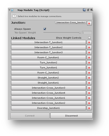
Note: The selected junction in the dropdown will be highlighted with a pink wire box in the scene view, while other junctions remain teal.
The following properties/controls can be used to customize individual junction behavior:
Always Spawn: If enabled, the junction will always be included in the generation random selection. When disabled, the ‘No-Spawn’ Weight control will become available.
‘No-Spawn’ Weight: When Always Spawn is disabled, this value indicates the relative chance that this junction will be skipped during generation i.e. Value of one (1) will cause a module to never spawn at this junction. (Note, this also affects the spawn chance of “detail” modules, discussed later.)
Show Weight Controls: When enabled, an “Override Weight” checkbox and slider will be shown below each linked module button. This allows fine tuning of the relative chance each linked module will be selected during generation.
The buttons for each linked module can be toggled, which will spawn that module at the junction location. This feature helps for testing, and can be used to build a specific item or map by hand and save to a resource file if required.
The system generates items as follows:
- A random module is selected.
- For each open junction in the selected module
- Instantiate a random connected module from the junction’s Linked Modules list.
- Perform step two for the newly instantiated module. (Each iteration of this loop is considered a “span.”)
- Spawn Details (optional)
- Build Navmesh (optional)
- Apply Lightmaps (optional)
- Pre-baked lightmaps will be applied to associated prefabs in the Awake() method of the Monobehavior lifecycle (described later).
- Finalize (optional)
- box colliders and map module tag components on modules are destroyed. This is considered the cleanup stage when the item will no longer be modified/expanded, etc.
Note: Steps one through five can be tested in-editor, but finalization can only done programmatically.
The following sections describe setup and configuration of optional steps.
To close-off unused junctions of your item or map when the span limit is reached, you can add “Detail” modules to the system, and connect them to the same junctions as main modules. These can be closed doors, walls, or otherwise “cap” prefabs.
Details are added and connected to junctions in the same way as main modules, except they have a separate section in the ProcMod asset. Use the [New Detail] button to add detail prefabs.
Note: Details module prefabs do not require box collider(s) at the root, and are not checked for collision with other modules during generation.
Detail modules can also be used to add uniqueness to any module. Simply connect multiple detail modules to a single junction within a main module, and one will be selected from among them during generation. Common details may include level design features (props, destructible objects, pickups, etc.), and/or enemies.
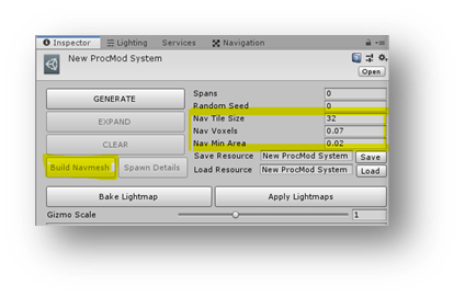
When using ProcMod to generate scene content that contains AI agents, the system can bake a NavMesh surface after the scene is generated. This can be tested in the Unity Editor by generating an item, configuring the navigation-related settings on the ProcMod system, then [Build Navmesh]:
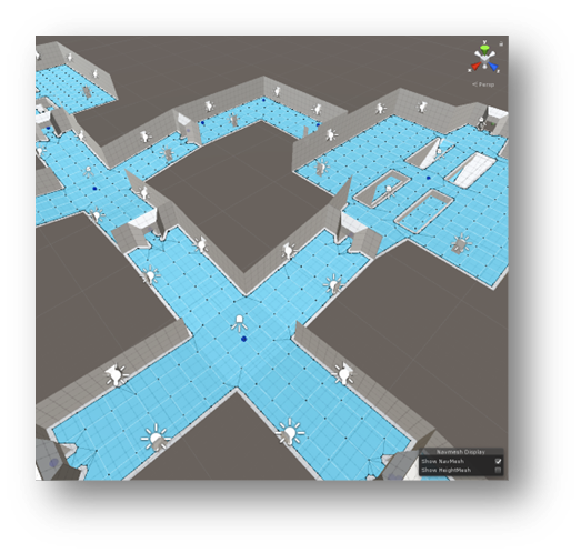
To view the baked mesh in the scene view, open the Navigation window (Window > AI > Navigation).
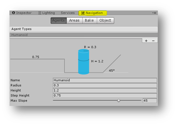
ProcMod uses settings on the first agent type in the “Agent Types” list when building the NavMesh.
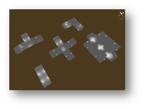
ProcMod can bake lightmap data into prefabs during design/editor time. The demo scene included in the package uses this feature by adding baked lights to each module prefab. The following steps will detail the basic application:
- In an empty scene, place one of each of the lightmapped prefabs into the scene view.
- Space modules enough to avoid lights in one module affecting other modules.
2. Use [Add Component] in the inspector to add PrefabLightmapData to each prefab.

- Apply All overrides using the “Overrides” dropdown.
3. Configure the lighting environment on the Window > Rendering > Lighting Settings page.
4. Select the ProcMod asset, and click [Bake Lightmap] to bake lightmaps into the prefabs.
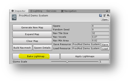
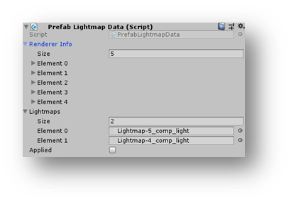
Once the bake is complete, the PrefabLightmapData component will have references.
5. Generate a new object and click [Apply Lightmaps] to update the current scene prefabs.
Note: Baked prefabs have lightmaps applied in the Awake() method of the Monobehavior lifecycle.
ProcMod can save and reload generated configurations in the following ways:
- Generated in-editor and saved as resources to load during runtime.
- SaveMapToResource()
- LoadMapFromResource()
- Generated at runtime, saved and loaded using the persistent data storage of the device.
- SaveMapToDisk()
- LoadMapFromDisk()
After generating an item in the Unity Editor, the all modules and details can be saved to a resource using the Save/Load Resource sections of the ProcMod asset.
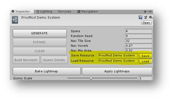
Use the text fields to set the resource name and click [Save] / [Load]. Resource are saved and loaded via the Assets/Resources/ProcMod folder. The API documentation has details on usage of these methods during runtime, and the demo scene included in the package is a working example.

